What is synchro?How is it related with stepper motor?
SYNCHRO
Normally, the rotor windings of a wound rotor induction motor are shorted out after starting. During starting, resistance may be placed in series with the rotor windings to limit starting current. If these windings are connected to a common starting resistance, the two rotors will remain synchronized during starting.This is usefull for printing presses and draw bridges, where two motors need to be synchronized during starting. Once started, and the rotors are shorted, the synchronizing torque is absent. The higher the resistance during starting, the higher the synchronizing torque for a pair of motors. If the starting resistors are removed, but the rotors still paralleled, there is no starting torque. However there is a substantial synchronizing torque. This is a selsyn, which is an abbreviation for “self synchronous”.
STEPPER MOTOR
A stepper motor is a “digital” version of the electric motor. The rotor moves in discrete steps as commanded, rather than rotating continuously like a conventional motor. When stopped but energized, a stepper (short for stepper motor) holds its load steady with a holding torque. Wide spread acceptance of the stepper motor within the last two decades was driven by the ascendancy of digital electronics. Modern solid state driver electronics was a key to its success. And, microprocessors readily interface to stepper motor driver circuits.
INCREMENTAL ENCODERS

Here Kdt represents the gain of the device and the truncated value y(kT) is subsequently differentiated.
For instance, if the input to the PG represents the position/displacement in radians, the unit of Kdt is (pulse/rev). Hence the units of y(kT) are pulses and after differentiation , we obtain the velocity signal y’(kT) in (pulses /T). [2]
References:
- http://engknowledge.com/
- G.A.Perdikaris, Computer controlled systems: Theory and Applications, Kluwer Academic Publishers, 14, 1996
What do the poles and zeros contribute to in the control system ?
Poles and Zeros of a transfer function are the frequencies for which the value of the transfer function becomes infinity or zero respectively. The values of the poles and the zeros of a system determine whether the system is stable, and how well the system performs. Control systems, in the most simple sense, can be designed simply by assigning specific values to the poles and zeros of the system.
Physically realizable control systems must have a number of poles greater than or equal to the number of zeros. Systems that satisfy this relationship are called proper. We will elaborate on this below.
Let's say we have a transfer function defined as a ratio of two polynomials:
Where N(s) and D(s) are simple polynomials. Zeros are the roots of N(s) (the numerator of the transfer function) obtained by setting N(s) = 0 and solving for s.
Poles are the roots of D(s) (the denominator of the transfer function), obtained by setting D(s) = 0 and solving for s. Because of our restriction above, that a transfer function must not have more zeros then poles, we can state that the polynomial order of D(s) must be greater then or equal to the polynomial order of N(s).
•Example •Consider the transfer function:H(S)=(s+2)/(s2+0.25) •We define N(s) and D(s) to be the numerator and denominator polynomials, as such: •N(s) = s + 2 •D(s) = s2 + 0.25 •We set N(s) to zero, and solve for s: •So we have a zero at s → -2. Now, we set D(s) to zero, and solve for s to obtain the poles of the equation: •And simplifying this gives us poles at: -i/2 , +i/2. Remember, s is a complex variable, and it can therefore take imaginary and complex values.
REFERENCES:wikipedia and control engg. main text
Consider the second-order system given by:
G(s) =1 / ((s+p1)(s+p2)) p1 > 0, p2 > 0
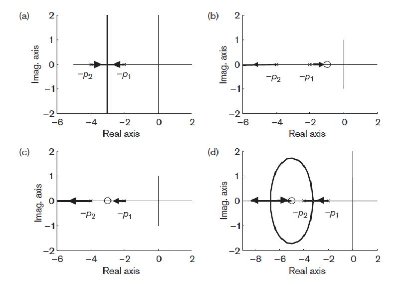
The poles are given by s = –p1 and s = –p2 and the simple root locus plot for this system is shown in Figure . When we add a zero at s = –z1 to the controller, the open-loop transfer function will change to:
G1(s) =K(s+z1) / ((s+p1)(s+p2)) , z1>0
 Effect of adding a zero to a second-order system root locus.
We can put the zero at three different positions with respect to the poles:
1. To the right of s = –p1 Figure (b)
2. Between s = –p2 and s = –p1 Figure (c)
3. To the left of s = –p2 Figure (d)
(a) The zero s = –z1 is not present.
For different values of K, the system can have two real poles or a pair of complex conjugate poles. Thus K for the system can be overdamped, critically damped or underdamped.
(b) The zero s = –z1 is located to the right of both poles, s = – p2 and s = –p1.
Here, the system can have only real poles. Hence only one value for K to make the system overdamped exists. Thus the pole–zero configuration is even more restricted than in case (a). Therefore this may not be a good location for our zero,
since the time response will become slower.
(c) The zero s = –z1 is located between s = –p2 and s = –p1.
This case provides a root locus on the real axis. The responses are therefore limited to overdamped responses. It is a slightly better location than (b), since faster responses are possible due to the dominant pole (pole nearest to jω-axis) lying further from the jω-axis than the dominant pole in (b).
(d) The zero s = –z1 is located to the left of s = –p2.
By placing the zero to the left of both poles, the vertical branches of case (a) are bent backward and one end approaches the zero and the other moves to infinity on the real axis. With this configuration, we can now change the damping ratio and the natural frequency . The closed-loop pole locations can lie further to the left than s = –p2, which will provide faster time responses. This structure therefore gives a more flexible configuration for control design. We can see that the resulting closed-loop pole positions are considerably influenced by the position of this zero. Since there is a relationship between the position of closed-loop poles and the system time domain performance, we can therefore modify the behaviour of closed-loop system by introducing appropriate zeros in the controller. [1]
References:


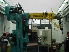
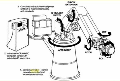
 An industrial robot is officially defined by ISO as an automatically controlled, reprogrammable, multipurpose manipulator programmable in three or more axes.


